Elevator Test Tower

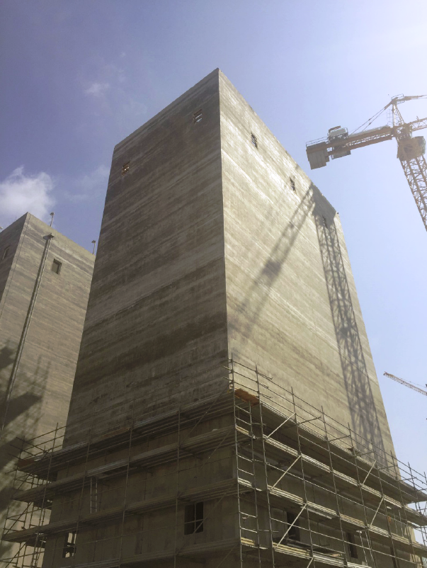
Atlanta, Georgia, United States – Elevator Shaft

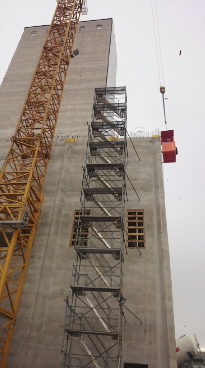
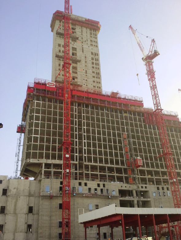
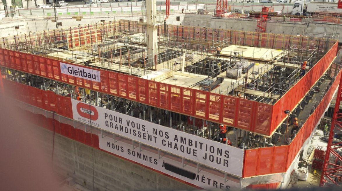
Brasfield & Gorrie was hired by ThyssenKrupp Elevator Company to construct a new elevator test tower in Atlanta, GA. At 400 ft / 121m it is the tallest such tower in the Western Hemisphere. To speed completion, the team chose the slipform method of construction. With outside tower dimensions of 74 ft x 56 ft, it took about eight weeks of continuous slipforming to complete the tower. This saved close to three months of construction time compared to other construction methods. Brasfield & Gorrie hired a specialist subcontractor for the actual slipform works.

Elevator Test Tower
New Elevator Test Tower – ThyssenKrupp

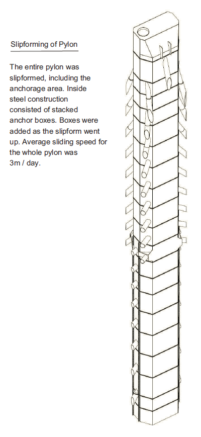
The slipform design had to accommodate nearly 190 openings and more than 3,300 embedded plates for interior and exterior structural steel framing. A continuous concrete supply of at least 5.5 cy per hour was needed to keep the slipforming on track. The concrete was bucketed to the work point by tower crane, which was also used for delivering the rebar, embeds and other supplies. The 4 ft tall slipform was hydraulically lifted by about an inch every 15 minutes. Soon, the tower began to rise at a rate of about 7.5 ft per day, with an average of 30 workers on the platform at any one time. The process was completed in 54 days with no recordable safety incidents.

Elevator Test Tower
Slipform Work Platform

Tapered Rectangular Conical Structure

Shin Seoncheong, South Korea – Tapered Rectangular Chimney

Global Chimneys Co. Ltd. hired a specialist contractor to slipform this new chimney structure. The sliding operation was performed during 2017. The tapered rectangular shape makes for a unique and spectacular tower-like structure, made possible by the latest advances in slipform technology. The overall height is 148 m and the base dimensions of 20 m x 20 m taper off to 12 m x 12 m at the top. The wall thickness reduces from 0.90 m at the bottom to 0.35 m at the top.

Tapered Tower
Tapered Rectangular Chimney – Height 148 m

While this particular structure is a chimney, its shape could equally be applied to a tall bridge pier, especially in regions with high seismic activity. The tapered shape would increase the flexural stiffness of such a pier, reduce transverse superstructure deflections and enhance the dynamic performance of the overall bridge. Slipforming is the only building method that can economically produce such a tapered, rectangular shape. The technology was developed and perfected for the slip form construction of offshore gravity base structures and then extended to include almost any kind of vertical concrete structure.

Some basic drawings about the slip form system of construction can be found here. Slipforming has proven to be a very dynamic and capable technology, rapidly adapting to changing market needs and able to create structures that were unthinkable just a few years ago.

Flour Silo by Vertical Slipforming

Saalemühle Alsleben GmbH – New Flour Silo

Alsleben a.d. Saale, Germany – General contractor Industriebau Wernigerode GmbH hired a specialist subcontractor to slipform the new flour silo Nr. 3 for agricultural company Saalemühle Alsleben. The work was executed during 2015 and 2016. Constructed in two phases, the bulkier lower section was slipformed to a height of 19.49 m, followed on top by a more slender section slipformed to a height of 47.16 m.

Slipform construction of a flour silo

New Flour Silo Nr. 3 built for Saalemühle Alsleben GmbH.

LNG Tank

Port of Tahkoluoto, Finland

LNG Tank

LNG Tank slipformed by a specialist contractor.

Finland’s first Liquefied Natural Gas (LNG) Terminal is being built by Skangas at the oil and chemical harbor of the Port of Tahkoluoto in Pori, on the west coast of Finland. The estimated completion date for the terminal is fall of 2016. Total LNG storage capacity will be 30,000 cubic meters.

LNG Tank

Tank during slipforming showing radial guide ropes.

The LNG tank has a final height of 35 m and an outside diameter of 42 m. The walls of the tank were slipformed truly round with the help of radial wire ropes coming together at the geometric center of the tank. Additional ground-based lasers ensured the tank was constructed true and vertical and also confirmed perfect roundness. By adding enough lasers around the perimeter, there were no deviations from perfectly round to speak of. This is an important step in achieving the desired accuracy in tank geometry. High precision is required in the wall geometry as the steel dome has to accurately fit the inside of the tank. These steel roofs are normally assembled on the ground and lifted in place with hydraulic heavy lifting techniques or with internal air pressure. Welders then attach the roof to a steel ring embedded in the concrete wall. A final concrete layer is poured over this steel dome to complete the tank structure.

LNG Tank

Steel roof being lifted into place.

The general contractor on the project is a partnership of Neste Jacobs Oy, KVL-Tekniikka Oy and FCC Industrial. Concrete subcontractor Destia Ltd. hired a specialist company for slipforming the tank walls. Slipforming was completed in 2014. Safety during construction was a high priority and slipforming proved to be very safe once again, as during slipforming the formwork is supported at numerous points at all times and is never released from the structure below.

Mill Building

Jazan B-Mill, Saudi Arabia

mill building with silos

Jazan B-Mill – Silos slipformed by a specialist contractor

Shown here are two silos that form part of the Jazan B-Mill complex, a flour mill with attached silos that has a production capacity of 600 tons per day. The owner is GSFMO (Ministry of Agriculture of Saudi Arabia).

The general contractor for the concrete work was CEM Estero S.p.a. of Italy, operating from its offices in Riyadh. The contractor hired a specialist contractor to slipform these two silos in late 2015. The slipform height was 28.3 m. Each silo shell was completed in under a week, by working around the clock, pouring concrete 24 hours a day.

New Solar Tower

Solar Tower
Ashalim Solar Thermal Station with 240 m Tower. Image by Megalim Solar Power Ltd.
New Solar Tower – Negev Desert, Israel

The world’s tallest solar tower at 787 ft will be built this year in the Negev Desert, Israel. 50,600 computer-controlled mirrors surrounding the tower will track the sun and point the energy to the top of the tower, where superheated steam will be produced for driving a turbine. When finished, the tower and mirrors will be able to produce 121 MW of power. The $800 million project is being built by a joint venture company owned by Brightsource Energy (25%), GE Alstom (25%) and NOY Infrastructure & Energy Investment Fund (50%).

The developer-builder of this project, Megalim Solar Power Ltd, hired a specialist company to slipform the tower shaft to a height of 200 m. After that, the 2500 ton boiler will be lifted into place to complete the tower.

Some basic drawings of the slipforming process can be found here.

Silo Construction

Silo Work – Guacolda, Chile

silo

Slipforming of two silos in Guacolda, Chile – 2014

Guacolda power plant in northern Chile. Züblin International GmbH, Chile SpA hired a specialist company to slipform these two silos, which are 40 m tall. They represent a typical application for slipforming technology. Recent advances in slipforming allow for much more complex shapes to be built, such as conical structures with parabolic curves from bottom to top.

silo

Silo shell completed by the slipform subcontractor – 2014

Bridge Pylons

St. Petersburg, Russia

bridge pylons

Petrovsky Fairway Cable-Stayed Bridge, St. Petersburg, Russia

Pictured here are the bridge pylons for the Petrovsky Fairway cable-stayed bridge, which is a crucial link in the St. Petersburg Western High Speed Diameter Project. This is the largest PPP road construction project in the world today and the first urban high-speed toll motorway in Russia.

Elba Yaritim Sondazh Inshaat, the general contractor on this project, hired a specialist subcontractor to slipform the two bridge pylons. The pylons are approximately 114 m tall with outside dimensions of roughly 5.0 m x 6.0 m per leg. The pylons were completed in 2014. Slipforming was chosen because of the speed of construction and the resulting structural durability, as the towers have no construction joints or form-tie holes.

Anchorage Area

The cable anchorage area required the installation of welded steel boxes, which nowadays is the preferred method for defining the intricate stay pipe and bearing plate geometry for each cable.

The slipform was stopped at the underside of the first welded box, to insert steel supports into the wet concrete. These supports were then used for leveling and orienting the box in relation to the bridge.

At that point, the inside form was abandoned and slipforming continued with the outside form only, which ran flush with the ends of the stay pipes. These pipes were cut at compound angles to match the concrete surface.

As the slipform climbed, steel boxes were added. Bolts were used initially for connecting and adjusting the boxes, followed by final welding.

This particular design anchored the stay cables inside the tower. No cable saddles were used. The entire pylon was slipformed at an average speed of 3m / day, including the anchorage area.

bridge pylons

Bridge pylons being slipformed

Cable Car Towers

Cable Car Transportation Complex, Vietnam

cable cars tower

Conical tower slipforming with 15 degree incline, by a specialist contractor.

Shown above are the three-legged towers for the Queen Cable Car aerial tramway installation in Ha Long, Vietnam. This record-setting cable car system is part of the Ocean Park Project in the Bai Chay area. The project aims to boost tourism in Ha Long Bay.

Completed in 2015, the aerial tramway sports massive 230 passenger cabins and concrete support towers up to 185 m tall. The individual tower legs start out with a diameter of either 4.0 m or 5.0 m, tapering all the way to the top. They also maintain a constant wall thickness of 0.35 m along their height. The maximum inclination is 15 degrees from vertical.

To build the record-setting cable car towers, the owner and general contractor, Sun Group of Vietnam, hired a specialist subcontractor for slipforming the conical legs of the towers. They slipformed two towers with three legs each, and also provided the heavy lifting services required for erecting the precast strut triangles, which stabilize the tower legs.

cable car towers

Conical tower slipforming and heavy lifting of precast strut triangles for stabilizing the tower legs.

High Rise Building Cores

High Rise in Paris, France

High Rise Construction

High Rise Construction – Slipforming of the Building Core – 180 m tall / 590 ft

High rise construction can greatly benefit from the use of vertical slipforming. Shown above is the new Palais De Justice currently being built in Paris, France. Most tall buildings have one or more concrete cores that provide lateral strength to the building. They also house the stairs and elevators. These cores can be rapidly built by using the slipform method of construction. Doorways and openings are easily added by inserting block-outs into the slipform as it rises. The above high rise core was slipformed by working day shifts only. However, slipforming is most efficient when working around the clock, 24 hours per day, using two or three shifts. Typical speeds are 3m to 5m per day, but up to 10m per day can be achieved if workers are well coordinated and not limited by material supply or concrete quality.

Slipforming is extremely safe, as the slipform setup always remains connected to the structure. The two work platforms provide a safe and predicable environment for the workers. The lower platform is used for finishing the concrete to the desired surface quality. Tarpaulins can also be suspended from the lower platform. These shield the fresh concrete from direct exposure to the sun and wind during the initial curing period.

A specialist slipform subcontractor was hired by Bouygues Travaux Publics of France to provide the slipform equipment and onsite supervision for this project, including geometry control.