Concrete Slipform Construction – Typical Details and Cross-Sections
Concrete slipform construction was initially developed in the United States during the end of the nineteen’s century to construct uniform (cylindrical) concrete silos in the Midwest. The technology has advanced rapidly during the last two decades, to the point where much more complex shapes can now be slipformed, such as conical towers and also shafts that change shape from round to near square, as was used on the Hebron Offshore Gravity Platform.
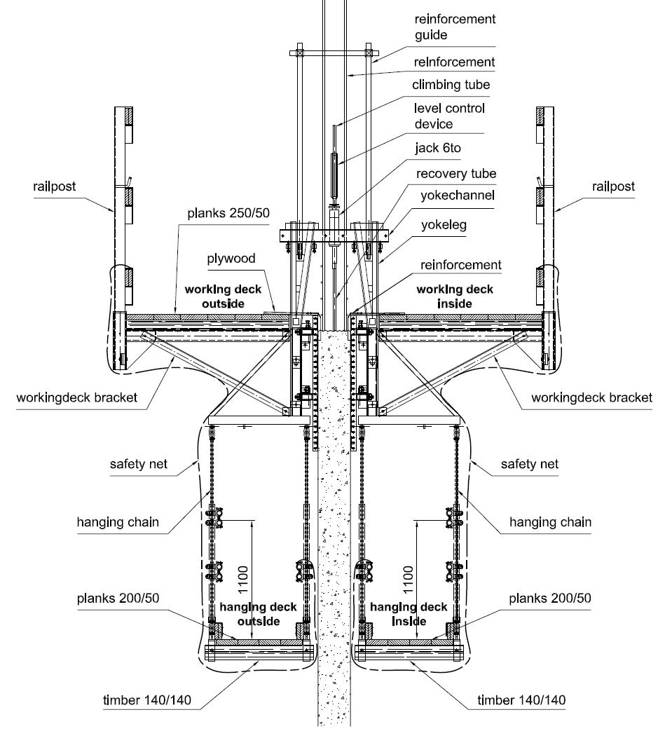
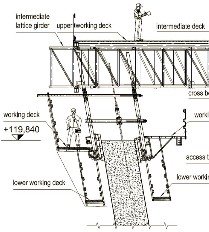
As can be seen above, the slipform always remains connected to the structure and is thus extremely safe. Wind forces are minimal because of the low overall height of the system and those forces are shed quickly to the concrete structure being built. The work environment is very predictable and unchanging for the crew. Very little climbing is required and mostly limited to accessing the lower finishing platform.
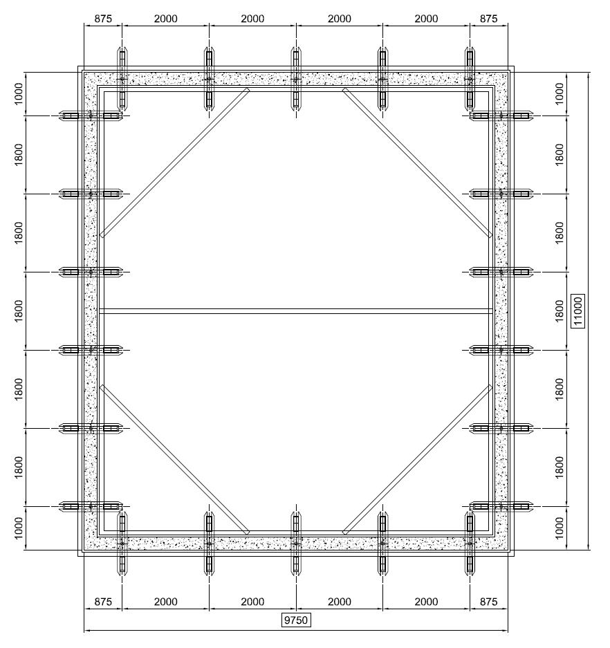
The slipform yokes are placed at regular intervals around the walls being slipformed. They take the pressure of the wet concrete directly, thus no form ties are required and also no patching of tie holes. The jacking cylinders are typically of 6 ton or 12 ton capacity. The jacking rods are made of a special steel that works in harmony with the jack grippers. If the jacks do not grip the rods properly and consistently, the slipform operation will not work.


